Programmable Logic Controllers: Ladder Logic and Symbology

1.00 Hr
SKU: ELPLLS0CEN

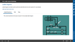
Ladder diagrams have been used to symbolically describe electrical control (PLC) systems for many decades. Early in the development of PLCs, it was decided to use ladder diagrams in their programming interface as well. This was done so that users of PLC systems would be able to see the program in a form that they were familiar with. Virtually all PLCs still use ladder diagrams. This course examines how PLCs use ladder diagrams to perform logic functions and the symbology involved.
Vector Solutions has a long history of providing industry-specific content for its customers. While this course and its content remain accurate and functional within our systems, the look and feel may not match our more modern offerings.

Programmable Logic Controllers: Ladder Logic and Symbology

Course Details

Learning Objectives

  • Describe parts of electrical ladder diagrams.
  • Identify common symbols used on ladder diagrams.
  • Describe using multiple devices on a rung.
  • Explain rung numbering and cross-references.
  • Explain differences between PLC and hard-wired ladder scans.
  • Describe JMP and jump to subroutine (JSR) instructions.
  • Specs

    Course Level
    Intermediate
    Languages
    English
    Compatibility
    Audio, Video, MobileReady

    Author | Vector Solutions

    With over two decades of experience designing advanced 3D animated courseware and developing our proprietary learning management software, we pride ourselves by having developed over 1,000 safety and operations training modules, which have helped train over 250,000 workers worldwide. Our highly experienced team provides the industry with a simple and high-quality means of training their workforce. Whether your team consists of 25 people or an enterprise with thousands, we’re here to help.

    Trusted by 24,000+ Industry Leaders